
1. The free electron laser FLASH
Sebastian Roling, Michael Wöstmann
The Deutsche Elektronen-Synchrotron DESY is a research center for fundamental natural science research. A part of DESY is the HASYLAB (Hamburger Synchrotronstrahlungslabor, "Hamburg Synchrotron radiation Laboratory"). It is an institute for research with synchrotron radiation at DESY. The laboratory adjoins to the storage ring DORIS and PETRA in order to be able to use the generated synchrotron radiation for research. It also includes the "Free Electron LASer in Hamburg" (FEL), called FLASH. In contrast to storage rings FELs generate laser-like radiation from synchrotron radiation, see explanation below.
FLASH was the first FEL producing light in the vacuum ultraviolet (VUV), extreme ultraviolet (XUV) and soft X-ray range of the spectrum. Meanwhile there are some few other FELs for this spectral range in operation, like LCLS in Stanford, USA (hard x-rays); Fermi@elettra in Trieste, Italy; and SCSS in Japan. Currently another FEL is under construction in Hamburg, the European XFEL, whose wavelength will be pushed into hard X-rays.

@ DESY 2010
In a cooperation with the Helmholtz-Zentrum Berlin (HZB) formally BESSY, and DESY we built an split-and-delay unit for FLASH to provide time-resolved experiments with XUV pump XUV probe radiation and to study the coherence properties of the FEL Beam.
Additionally we investigate surface reactions triggered by FLASH. Thereby one learns about mechanisms of surface reactions for the creation of molecules in the interstellar medium.
Principle creation of the FLASH radiation
Synchrotron radiation is generated by accelerated charged particles. In storage rings, where relativistic electron bunches are kept on a circular orbit, it spans from the infrared (IR) to the hard X-ray spectral range depending on the parameters of the ring. But this kind of synchrotron radiation is incoherent and not monochromatic, it does not possess the properties of laser light. To achieve coherent and monochromatic synchrotron radiation an undulator is needed. Undulators are specially designed configurations of alternatively polarized magnetic fields. Electron bunches passing an undulator are carried on a slalom-like orbit in a way that the radiation they emit can interact with themselves.
The radiation spontaneously emitted by the wiggling electrons in an undulator can serve as starting point of the FEL process. This radiation is amplified later during the passage of the electron bunches through the undulator, generating short, monochromatic light pulses with a short coherence time, depending on the wavelength.
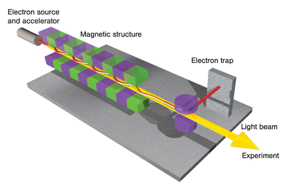
Fig.1: Electrons passing an undulator and emitting radiation. © DESY 2006
For X-rays and XUV radiation there are no suitable mirrors with high reflectivities to operate an oscillator, which is one of the main restrictions operating a conventional Laser in this regime. A sufficient amplification has to occur during one passage through the undulator. Therefore a very long undulator is used. At FLASH the undulator is 27 m long. In long undulators another process comes into play, which leads to a massive amplification of the radiation, many times more than in short undulators. This process is called microbunching. Relativistic electron bunches passing an undulator have a much higher spatial extension than one wavelength of the radiation they emit. This leads to some electrons loosing energy to the light wave, falling back within the bunch and some gaining energy from the wave, making up ground in the bunch. The consequence is a concentration of electrons at certain positions, the microbunches. These microbunches are within a distance to each other of exactly one wavelength of the radiation. This causes a massive amplification because at the point the microbunches are formed, all electrons are moving coherently and therefore radiate and amplify also coherently. The process comes to an end when Coulomb forces restrict a further compression of the microbunches. At this point, which is called the regime of saturation, energy is pumped to the radiation back and forth by the microbunches. The whole amplification process of the radiation based on the formation of the microbunches induced by spontaneous undulator radiation is called Self-Amplified Spontaneous Emission (SASE).
2. Measurement of the coherence properties of the free electron laser FLASH
Coherence is a measure of the correlation properties of different electromagnetic wave fields. For first order coherence the mutual correlation function Γ describes the coherence of an electromagnetic field E between two positions r1 and r2 at different times t and (t+τ):
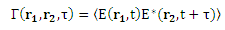 (1)
(1)
For a fixed distance (ri - rj) this simplifies to the mutual time correlation function:
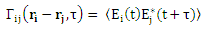 (2)
(2)
The absolute value of the normalized correlation function γ12(τ)
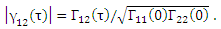 (3)
(3)
can be measured as the visibility V of the interference fringes of two interfering partial beams. The visibility V is connected to the normalized correlation γ12(τ) via
 (4)
(4)
where I1 and I2 are the intensities of the interfering partial beams and Imax and Imin are the maximum and minimum intensities of the interference fringes, respectively. The coherence time τc can be defined as the half width at half maximum [HWHM] of γ12(τ).
For an experimental measurement of the temporal coherence ideally time-delayed amplitude replicas of the FEL pulses should be brought to interference. However, the lack of amplitude splitting optical elements in the x-ray regime permits only the use of wavefront splitting mirrors in grazing incidence. These elements can then be applied in a broad spectral region. Such a beam splitter and delay unit (autocorrelator) is shown schematically in figure 1 (a).
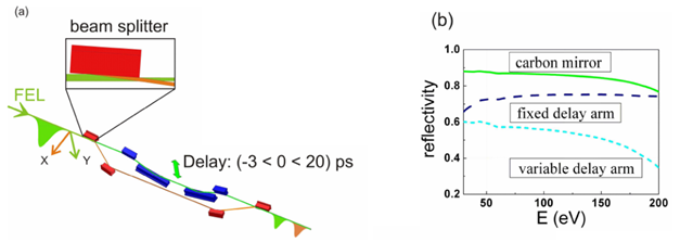
Fig. 2: (a) Schematic drawing of the layout of the autocorrelator. Grazing angles of 3° and 6° for the fixed and variable delay arms, respectively, are employed to ensure a high reflectivity of the soft x-ray radiation. (b) Calculated reflectivity for amorphous carbon coated silicon mirrors for hν = 30 to 200 eV. The full green line shows the reflectivity of a single mirror for a grazing angle of 6°.
Based on geometrical wave front beam splitting by a sharp mirror edge and grazing incident angles the autocorrelator covers the fundamental energy range of FLASH (20 - 200 eV) with an efficiency of better than 50%, see figure 1 (b). Grazing angles of 3° and 6° for the fixed and variable delay arms, respectively, are employed to ensure a high reflectivity of the soft x-ray radiation. Looking in the propagation direction the beam splitter with a sharp edge reflects the left part of the incoming FEL pulse horizontally into a fixed beam path. The other part of the beam passes this beam splitting mirror unaffected and is then reflected vertically by the second mirror into a variable delay line. A variable time delay between -5 ps and +20 ps with respect to the fixed beam path can be achieved with a nominal step size of 40 as. The seventh and eighth mirror reflect the partial beams into their original direction.
Alternatively, small angles can be introduced to achieve and vary a spatial overlap of the partial beams.
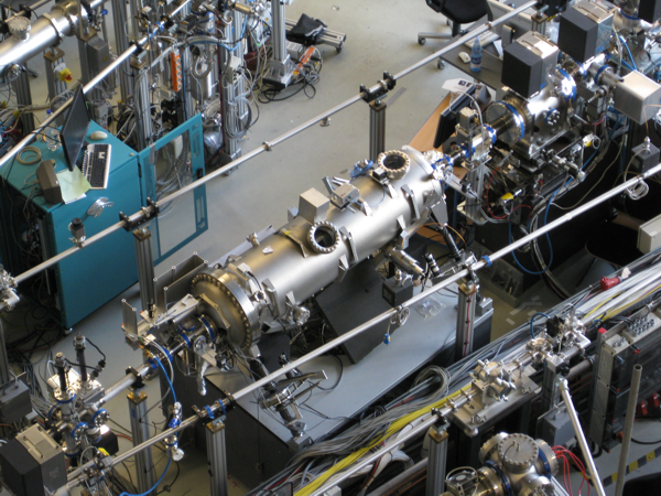
Fig. 3: The autocorrelator installed at beamline 2 at FLASH.
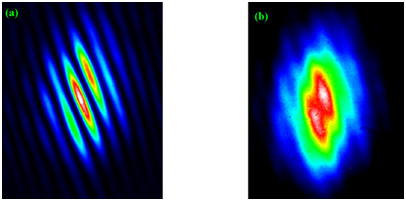
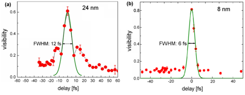
Scanning now the delay between the two pulses and calculating at each time step the visibility of the interference fringes (applying Equation 4) the temporal coherence properties of FLASH pulses are investigated. For zero delay almost fully modulated interference fringes as show in in figure 3 (a) can be observed. With increasing delay these fringes vanish, see figure 3 (b). Figure 4 shows the time delay dependence of the average visibility observed for two different wavelengths, λ = 23.9 nm and λ = 8 nm. Each data point (red dots) is the average of the visibility of ten single exposure interference pictures. In figure 4(a) the (averaged) visibility of V = 0.63 at zero time delay rapidly decreases as the time delay is increased. The central maximum of the correlation can be described by a Gaussian function (green line) with a width of 12 fs (FWHM). Then a coherence time corresponding to half of the full width of τcoh = 6 fs is obtained.
Figure 4 (b) shows the result from an analogous measurement at λ = 8 nm. From a Gaussian fit with a FWHM of 6 fs a coherence time of τc = 3 fs is obtained.
Further the autocorrelator can be applied to perform jitter-free pump-probe experiments in the VUV- and soft x-ray spectral regime. To guarantee a continuously good beam quality the facilities invest significant efforts into the transportation of radiation. One major reason for a possible disturbance of beam quality within the autocorrelator is an inhomogeneous loss of intensity of the reflected beam on the mirrors, due to radiation damage of their surfaces. As already mentioned carbon coated mirrors are used to guide the XUV beam through the autocorrelator. In experiments performed with a test substrate the surface was illuminated with multiple FLASH pulses below the damage threshold but higher than the expected fluence. The measurements indicate a change in the surface composition of carbon coated substrates under multiple pulse illumination. A change in optical reflectivity is evident depending on the number of pulses applied. Furthermore, a change in the spot size can be identified while a decrease of the carbon signal in taken Raman spectra depending on the rate of illuminated pulses is observed. Surprisingly, no explicit change in the surface height on the visible spots is detected with a profilometer and an atomic force microscope (AFM). Although no effects are visible in experiments performed with the autocorrelator further experiments should clarify these findings.
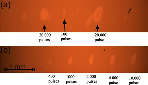
Figure 6. (a) + (b) Sequences of multiple exposures on a carbon coated silicon surface under an optical microscope. The number of pulses varies from 100 to 20.000 with a supplied fluence of 19 mJ/cm³ of FLASH under an angle of 10° to the surface normal at a wavelength of 21 nm. Under the optical microscope a change in reflectivity depending on the exposed number of laser pulses is visible [5].
3. A split-and-delay unit for the European XFEL
The emergence of new hard x-ray sources providing ultrashort and ultrabright light pulses allows for new classes of x-ray experiments. This is a great challenge for optical instrumentation. In addition to the already operating LCLS at the Stanford Linear Accelerator Center (USA) and SACLA in Japan the European XFEL is now under construction in Hamburg (Germany). Operating at electron bunch energies of 17.5 GeV the machine will provide photon energies between hν = 3 keV and hν = 24 keV at the undulator sources SASE1 and 2. Pulse energies of presumably Epulse = 2 mJ
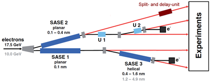
Fig. 7: A possible point of integration of the SDU into the beam line SASE2 100 m in front of the experimental hall
and a pulse duration on the order of Τpulse = 100 fs are expected. In the burst mode very high repetition rates of 2700 pulses at 4.5 MHz per burst at a repetition rate of 10 Hz are possible, due to superconducting accelerators. In order to gain information about the temporal properties of the x-ray pulses, like temporal coherence and pulse-duration, two jitter-free pulse replicas are required. Also for x-ray pump / x-ray probe experiments and for time-resolved diffractive imaging [6] a split- und delay unit is needed.
The high absorbance and the small reflectivity at large incident angles are severe limitations for optical instrumentation in the x-ray range and therefore demand for a grazing incident geometry. The optical concept will have to meet various requirements, like: High reflectivity, transmission of the whole spatial beam profile, delay with sub-fs resolution, a large delay range, and the wide photon energy range of the XFEL (5 - 20keV). These properties have to be achieved with a minimal disturbance of the beam position and direction, a high mechanical stability making a temporal resolution in the sub 100 attosecond regime feasible. The design and construction should of course incorporate elements, which allow a realization of the SDU in a practicable size.
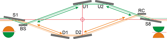
Fig.8: Schematic drawing of the optical layout of the x-ray split- and delay-unit.
In order to meet these requirements a point symmetric optical concept based on a geometrical wavefront beam splitter and multilayer Bragg coatings which permit larger grazing angles has been developed. The whole set-up of the optical pathway is schematically shown in Fig. 7. The XFEL beam enters the SDU from the left side and is reflected by the first mirror (S1) downwards in the direction of the beam splitter (BS). The lower green part of the beam is reflected into the upper delay arm while the upper orange part passes the sharp edge in the direction of the lower delay arm. The mirrors of both delay arms can be moved along the split beam direction in order to introduce a temporal delay between both partial beams. After the orange beam has passed the lower delay line it is reflected by the recombination mirror (RC) in the direction of the last mirror (S8). The green beam passes the sharp edge of the recombination mirror unaffected. Thus, in this point symmetric concept the recombination mirror acts as the counterpart of the beam splitter. The last mirror (S8) reflects both beams into their original direction. It should be noted that the beam shape of both arms is rotated by 180° due to the odd number of reflections. In order to perform experiments the beams will have to be overlapped. This can be achieved by slightly rotating the recombination mirror, RC.
As already mentioned the mirrors are intended to work at grazing incidence angles. For photon energies from hν 5 keV to hν 20 keV multilayers will be used on the mirrors which possess high reflectivity. Since for multilayers the grazing angle depends on the wavelength, the mirrors have to be aligned for different wavelengths.
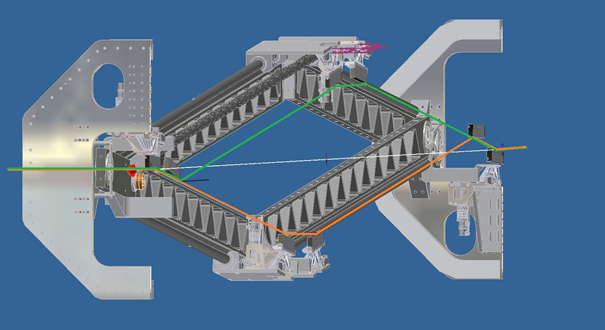
Fig. 9: Mechanical layout of the split- and delay-unit for the European XFEL.
The projected sub-fs resolution as well as the essential pointing stability of the partial beams demand an extensive mechanical stability of the 6 m long construction. For the SDU at FLASH an intrinsic mechanical stabilization of the entire system is achieved by increasing the stiffness of the whole system. Thereby vibrations are significantly reduced. To ensure the mechanical sturdyness all components are mounted inside an optical bench which consists of an octagonal structure of stainless steel. For the SDU for the European XFEL a similar octagonal structure will be utilized, see Fig. 7. The mechanical stability of the optical bench is further improved by supporting frames. As discussed before the FEL beam is divided geometrically and both partial beams travel along two paths whose lengths can be adjusted. The path-length difference of one beam with respect to the other and in consequence the temporal delay is changed by moving the mirrors of both arms along the 2.4 m long guide rails. With this a maximum delay of one branch with respect to the other of 2.5 ps at 20 keV and 23 ps at 5 keV is possible. In order to adjust the correct angles for different photon energies all mirrors are turnable and the angle of the guide rails is variable.
Since the whole system will be installed into an ultra-high vacuum chamber and due to the fact that the surfaces of the multilayer mirrors are very sensible, the construction work is done under cleanroom conditions, see Fig. 10.
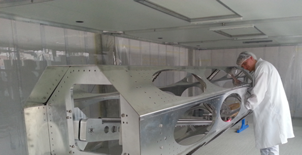
Fig. 10: Construction of the SDU under cleanroom conditions.
Publications
1. Mitzner, R.; Siemer, B.; Neeb, M.; Noll, T.; Siewert, F.; Roling, S.; Rutkowski, M.; Sorokin, A. A.; Richter, M.; Juranic, P.; Tiedtke, K.; Feldhaus, J.; Eberhardt, W. & Zacharias H., Spatio-temporal coherence of free electron laser pulses in the soft x-ray regime, Optics Express, 16, (2008) 19909-19919
2. Mitzner, R.; Sorokin, A. A.; Siemer, B.; Roling, S.; Rotkowski, M.; Zacharias, H.; Neeb, M.; Noll, T.; Siewert, F.; Eberhardt, W.; Richter, M.; Juranic, P.; Tiedtke, K. & Feldhaus, J., Direct autocorrelation of soft-x-ray free-electron-laser pulses by time-resolved two-photon double ionization of He. Physical Review A, 80, (2009), 025402
3. Roling, S.; Zacharias, H., Coherence of XUV laser sources, Coherence and Ultrashort Pulse Laser Emission, F. J. Duarte (Ed.), ISBN: 978-953-307-242-5,
http://www.intechopen.com/articles/show/title/coherence-of-xuv-laser-sources
4. Roling, S.; Mitzner, R.; Siemer, B.; Tiedtke, K.; Wöstmann, M.; Singer, A.; Vartanyants, I.A. & Zacharias, H., Temporal and spatial coherence properties of free-eletron laser pulses in the extreme ultraviolet regime, Physical Review Special Topics – Accelerators and Beams, 14, (2011) 080701
5. Siemer, B.; Hoger, T.; Rutkowski M.; Menneken, M.; Düsterer, S. & Zacharias, H., Multiple free electron laser pulse illumination of a carbon coated silicon substrate, Proc. SPIE, 8777, (2013) 87770F
6. Günther C.M.; Pfau, B.; Mitzner, R.; Siemer, B.; Roling, S.; Zacharias, H.; Kutz, O.; Rudolph, I.; Schondelmaier, D.; Treusch, R. & Eisebitt, S., Sequential femtosecond x-ray imaging, Nature Photonics 5, (2011), 99-102