Network Editor
The network editor is a graphical interface for the creation and modification of Voreen networks in a simple and intutive way.


The network editor is a graphical interface for the creation and modification of Voreen networks in a simple and intutive way.
The editor has about 20 different items the user can interact with. The most important ones will be explained here.
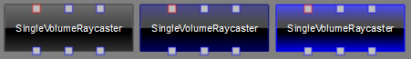
The image shows, from left to right, an unselected processor, a processor over which the mouse cursor is hovering, and a processor which was selected by mouse click in the editor.
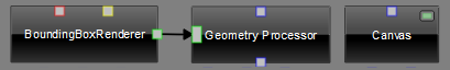
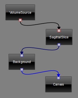
A processor can have several kinds of ports: inports are located on the upper side of each processor item, outports are found on the lower side. Coprocessor inports are placed on the left and coprocessor outports on the right. The color of a port indicates its type. In general only ports of the same color (i.e., the same type) can be connected.
The symbol in the right corner of a processor indicates an extra processor widget, e.g. the canvas of the Canvas processor. These widgets can be toggled by clicking this symbol.
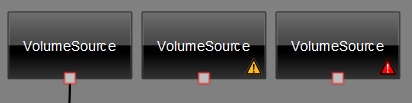
A processor can have three different states "ready", "not ready" and "not initialized" as seen from left to right in the image above.
| State | Visual Highlighting | Meaning |
|---|---|---|
| ready | no sign | The processor is ready to use. The process() function will be called during network evaluation. |
| not ready | yellow warning sign | The isReady() function returns false. The process() function will not be called during evaluation and the processor will not work properly. By default this state indicates not connected ports of the processor or missing input data and can be fixed by connecting the missing ports. |
| not initialized | red warning sign | The initialize() function of the processor has not been called yet or has thrown an exception. After loading a network each processor begins in this state. If the initialization fails it remains in this state. It indicates an error (e.g. not compiled shaders) which makes a proper functioning of the processor impossible. This state can normally not been fixed in the editor. |
For more information on the specific processor functions mentioned in the table see here.
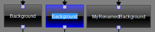
A processor can be renamed by selecting the processor and pressing F2 or by using the context menu by right clicking with the mouse on the processor item. The new name has to be unique in the network. Otherwise Voreen will add a number to the name.
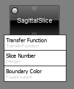

Properties of a processor are displayed by simple white rectangles with the propertys name and its type written on. To learn more about properties and how to interact with them see Linking Layer.
Connections can exist between ports and between properties. Normally they are directed, indicated by an arrow head on one side. An arrow head on both sides represent a bidirectional connection.
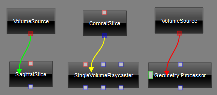
Like processors, connections can be unselected, hovered or selected (left). In most cases a color change informs the user if a connection can be made (right). Green means a connection is possible, whereas red indicates a connection is not possible. A yellow arrow is used for connections that can be created, but only with some modifications.
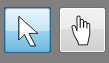
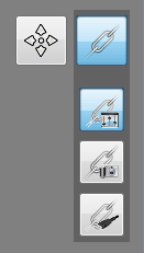
The navigation in the network editor has been optimized since Voreen 4.1 to have a better control by using two navigation modes in the upper left of the editor.
In arrow mode items can be selected, processors can be moved and connections can be built. This is the normal mode to modify and interact with the network.
To move the whole network the hand cursor (button two) can be used. Alternatively, pressing shift in the arrow mode will have the same result. In this mode no interaction with the network is possible. The arrow keys of the keybord are another option to navigate.
When the network becomes bigger it is necessary to zoom out. This can be achieved by using the + and - keys of the keyboard or by using the mouse wheel.

The two buttons in the lower left of the editor are used to arrange the network items. By clicking the first button the network will be centered so that every processor of the network is visible on the screen. It is useful to get an overview of the entire network.
With Voreen 4.4 a new feature has been implemented to arrange the network processors automatically. Clicking the second button will heuristically arrange the network as shown in the example below.
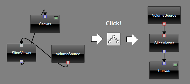
The user can change parameters of the heuristic in Options -> Settings -> Network Editor. Subnetworks can be arranged by selecting the processor items to sort and open the context menu by right clicking the mouse and selecting "Sort Subnetwork".

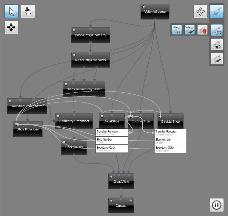
This is the main layer to build and modify a Voreen network. This layer is the default layer after starting Voreen. It can be selected by clicking the left button of the two buttons in the upper right corner.
In order to build a network, you can simply add new processors by dragging them from the processor list into the network editor. Processors can be connected via their different ports, however the port types have to match (different types are identifiable by their colors).
Ports are connected by pressing the left mouse button over an outport (located on the lower side of a processor) and dragging the appearing arrow to an inport (on the upper side of a processor). The arrow indicates whether a connection to the inport at the current mouse position is possible or not by changing its color to green respective red. Releasing the mouse button over a valid inport (green arrow) creates a connection.
Only in this layer processor items are movable.
Beside the Data Flow Layer this layer is the second main layer. It is devided into three sub layers, which are explained beneath. All sub layers allow linking of properties.
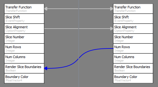
Linking properties means to synchronize their values. If a property changes its value, the changed value will be propagated along the link in the indicated direction. For instance, a change of the left option property called "Slice Alignment" will set the value of the right option property but not the other way round. If a link is bidirectional the properties are completely synchronized. In general all camera properties are linked bidirectionally to guarantee the same camera settings for all renderings in the network.
Normally only properties of the same type can be linked. Properties of different types, e.g. camera and boolean, cannot be linked. An exception are properties that can be converted. For example, an integer property can be linked to a bool property by simple casting.

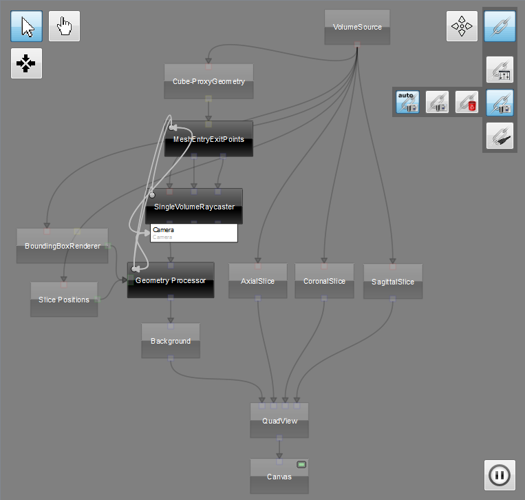
This layer can be used to link properties and see which properties have already been linked. By double-clicking a processor or clicking the small button in the upper left corner of the processor item a list of all linked properties of this processor will appear with connections to their linked properties.
By pressing the left mouse button over a processor and dragging the appearing connection to another processoer a new dialog will pop up.

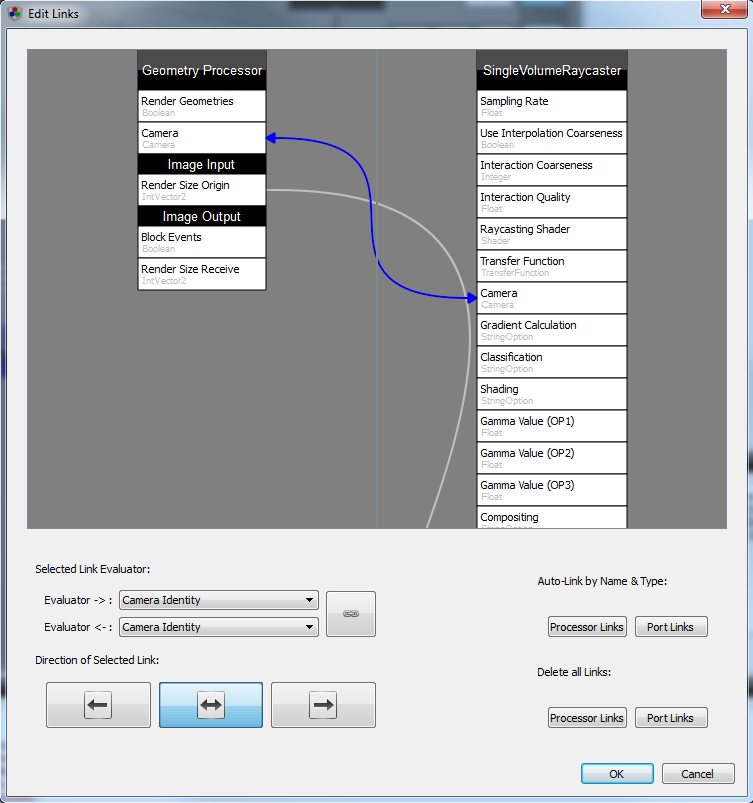
In this dialog all properties of the two processors and their ports can be seen. By clicking a property and dragging the appearing arrow to a property of the other processor a new link can be created. The color of the arrow indicates if a link between these properties is possible (see Connection). If the dialog is not closed via the ok button all changes will be discarded.

To keep the layer from becoming cluttered, the most common property links (i.e., camera and render size links) are hidden. They can be shown by clicking on the first two buttons. The third button simply deletes all existing property links.

This layer has the same functionality as the general linking layer except for the limitation to camera properties. Here, only processors with cameras can be selected and linked.

The first button toggles the auto camera linking, which is enabled by default. If a new processor is added to the network and auto camera linking is enabled all camera properties of this processor will be linked bidirectionally to all other camera properties of the network.
The second button links all camera properties. So, if the auto linking is disabled, the user can control when the linking should take place.
The last button simply removes all camera property links.
All these actions can also be used on a selection of processors using the context menu.
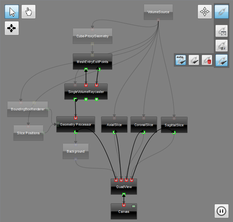

This layer was designed to get an easy management of render size links. All render ports with a size origin property or size receive property are highlighted in this layer. Origins are red and receiver are green. Like connecting ports in the Data Flow Layer two properties can be linked. A render size link should always go from an origin to a receiver (red to green). It is also possible to connect origin with origin and receiver with receiver. Connections from receiver to origin are not possible.

Like in the Camera Layer the first button controls the auto linking. If it is enabled each render port of a new processor will be linked automatically. If the linking cannot be done automatically the user will be informed by a warning in the debug console.
The second button links all render size properties manually.
The third button removes all render size links from the network.
All actions can also be controled by the context menu.

The button in the lower right corner of the editor indicates whether or not the network evaluator is enabled. By clicking pause the evaluator will be disabled and the render path will be stopped. It can be useful if connections are reconnected and expensive computations would be triggered. By clicking play the network will be evaluated again.gg