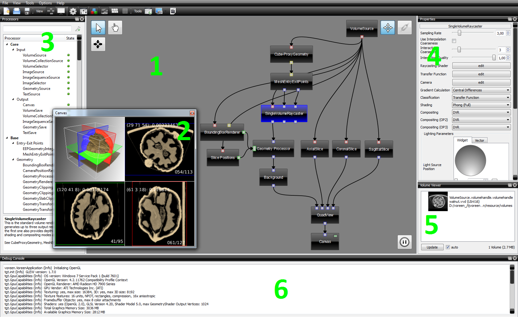
User Interface

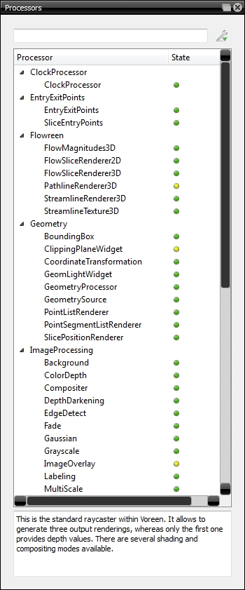
VoreenVE (Voreen Visualization Environment) is an application developed to construct processor networks for Voreen with an easy to use graphical user interface. The underlying concept is based on the idea of dataflow networks found in many image processing environments (see Concepts). VoreenVE allows to create complex rendering networks by simply dragging the desired processors into the workspace by using the mouse and connecting them by drawing the required connections.

Main Window

The following screenshot shows a typical state of a VoreenVE session:

Main Window Num 0

  • The green numbers indicate the main components:
    1. The network editor shows the current processor network and allows the user to modify it interactively.
    2. The canvas window shows the result produced by the current network. When there are multiple canvas processors in your network, also multiple canvas windows will appear.
    3. The processors list shows all available processors. These can be used to construct networks.
    4. The properties allow configuration of the selected processor.
    5. The volume container shows the currently loaded volumes.
    6. The debug console shows informations about the graphic card and informs the user about errors in the render path.

Modes

VoreenVE can be used in network mode and application mode. Rendering networks are constructed in the network mode. Switching to application mode hides the network editor and displays a larger visualization window. While the layout of the rendering network cannot be changed in application mode, it is still possible to modify properties of the processors in the network. However, property editing in the application mode is restricted to those properties, which have been set visible in the application mode confoguration (see below).

The same network in application mode looks like this:

Application Mode

Toolbar

The picture below shows the toolbar entries and their function.

Toolbar

  1. New Workspace - Create a new empty workspace.
  2. Open Workspace... - Load an existing workspace.
  3. Save Workspace - Save the current workspace.
  4. Network Mode - Switch to network mode.
  5. Application Mode - Switch to application mode.
  6. Processors - Hide/show the processor list (only available in network mode).
  7. Properties - Hide/show the property view.
  8. Volumes - Hide/show information about the currently loaded volume data sets.
  9. Debug Console - Hide/show a debug console containing log messages.
  10. Input Mapping - Hide/show the currently set input mapping for handling keyboard and mouse events.
  11. Render Targets - Hide/show the render target view, which shows intermediate rendering results, useful for debugging.
  12. Rebuild Shaders - Rebuild all currently load shader programs, which allows runtime shader editing with external programs.
  13. Snapshot - Save the content of one of the canvases or the network to an image file.
  14. Animation - Create animations using camera paths and save these animations as videos.

Canvas Interaction

Within each canvas you can rotate the camera by moving the mouse in the window while pressing the left mouse button. Using the mouse wheel or moving the mouse up and down while pressing the right mouse button, zooms the visualization. Pressing SHIFT and the left button moves the scene.

Canvcas

Properties

Properties are used to configure the selected processor. Changes become visible immediately in the rendering output. The visibility of each property in the application mode can be configured via the application mode configuration under Tools -> Application Mode Config while in network mode. By default, properties are not visible in application mode. In the application mode configuration, property groups can be created and properties can be added to these groups. The numbers in the application mode configuration for the individual properties are used to determine the order in which the properties appear in the application mode within the property group.

App Mode Config


Processor List

The processor list displays all available processors that can be used to build networks. You can search for processors by typing in the text box at the top. Furthermore, you can sort the list using the tool drop-down button, and the current code state of each processor is indicated by the colored dot. The text box in the bottom shows a brief description of the processor functionality.

Processors

You can add processors to your network by dragging them from the list into the network editor. Moreover, you can press the return key to either add the currently selected processor in the list or the topmost processor in the list when using the search bar.

Loading Data Sets

To load a data set select the VolumeSource processor in the network and click on the load volume button. After choosing a data file, the volume will be automaticly loaded and integrated into the render path.

Load Volume

Render Target View

The render target view can be used to inspect intermediate rendering results. A left-click enlarges a texture, a second click shrinks it again. With the context menu, alpha-channels and depth buffers can be accessed.

Render Target View